rpiarduinomusings

Raspberry Pi, Arduino, Sensors and the data they produce

Playing with a NodeMCU /8266 Debugging

Playing with a NodeMCU /8266 Debugging

For a deeper dive into the tools, I wanted to play with the NodeMCU /LUA environment (3) , while debugging a NodeMCU that I could not seem to get to take the arduino 8266 code.

The Arduino programming of 8266 was an extension of something I already was familiar with, but this one chip would not take a program through that method.
 I decided to look into the native code that comes from the factor, which is Based on NodeMCU.  I searched and found a tool called ESPlorer, but it was made in Russia.   At first I was a bit apprehensive, but then I found I could get the source code, meaning I could look at the code, and then setup from that which made me happy.
With this tool and a bit of learning from a couple of my favorite sites(1, 4), I was able to launch and run the code, and to get a response from the “wayward” chip.
I found a init.lua file that after inserting my SSD and passphrase, I was able to get it uploaded and executed:
=========================================================
–init.lua
wifi.setmode(wifi.STATION)
wifi.sta.config(“my-ssid”,”my-passphrase”)
wifi.sta.connect()
tmr.alarm(1, 1000, 1, function()
    if wifi.sta.getip() == nil then
        print(“IP unavaiable, Waiting…”)
    else
        tmr.stop(1)
        print(“ESP8266 mode is: ” .. wifi.getmode())
        print(“The module MAC address is: ” .. wifi.ap.getmac())
        print(“Config done, IP is “..wifi.sta.getip())
    end
end)
========================================================
Next I got a small webserver code to run:
srv=net.createServer(net.TCP)
srv:listen(80,function(conn)
    conn:on(“receive”,function(conn,payload)
    print(payload)
    conn:send(“<h1> ESP8266<BR>Server is working!</h1>”)
    conn:close()
    end)
end)
========================================================
ESPlorer interface as I execute the two code snippets::
Inline image 1
Web Page output:
Inline image 2
I hope to update this NodeMCU so that I can program it just as I did the earlier units, but this was a fun learning experience!
The ESPlorer user interface (in java)
Inline image 3
(1) http://randomnerdtutorials.com/esp8266-web-server/
(2) https://esp8266.ru/esplorer/
(3) https://nodemcu.readthedocs.io/en/master/en/flash/
(4) https://benlo.com/esp8266/esp8266QuickStart.html

8266 – We Need Control!

So far in this series,  I have show the build of sensors, and installed MQTT, configured Node-RED, and looked at a dashboard;  cool, but now I want to control things external to my system.

I have read and viewed several blog pages and YouTubes of people using home-built and commercial products to accomplish this goal.

Today, using a couple new libraries, I am exploring the Sonoff 8266 based relay units.  These are quite reasonably priced at $5-10 depending on where you procure them.

as-arrived

Disclaimer: I do not see an FCC marking nor a UL marking, so use at your own RISK. 

Disclaimer 2: I am programming this test via the FTDI Friend by AdaFruit, and I have modified this unit to deliver 3.3 volts versus the default 5 volts it comes from the factory with. Make sure you cut the line on the 5 v pad on the back of the board, and solder the 3.3 v pads together or you risk damaging the sonoff unit.  IF you are using a different unit, refer to the docvumentaiton that came with your unit to ensure you are only delivering VCC of 3.3 volts.

WARNING: Ensure you do not have any connectivity to the mains or AC voltage when you are doing this programming or wiring work!  Only do the programming when you have no AC connections! You can damage yourself and your equipment if you do not take this precaution.

Okay, that out of the way, let me tell you the setup of this unit for programming.

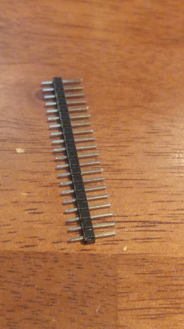
  1.  Open the Sonoff unit, remove the outer plastic shell to gain access to the board. You will be putting some type of connector onto the main board, which will allow your ftdi board to be connected.  I used a breakaway type header I had on hand. pin-header
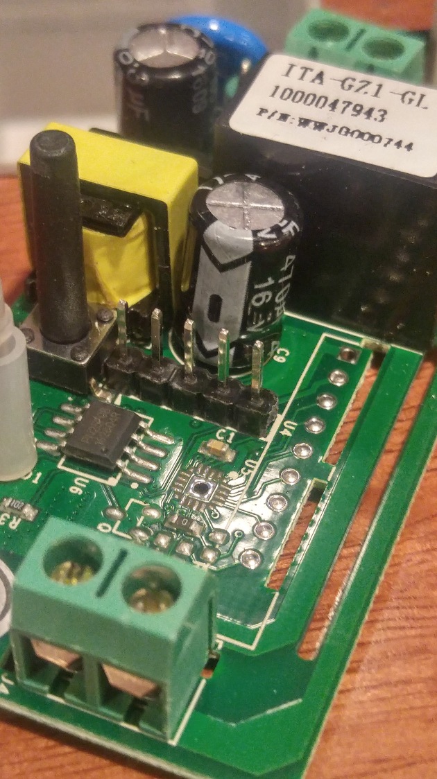
  2. Find the five pin holes in the middle of the board, and using putty or foam, hold the pin header in place and solder it up. located-for-soldering_ink_liheader-installed
  3. Connect up the 3.3 v to pin 1 which is closest to the black switch.  Connect up ground to pin 4.
  4.  Connect up the TX from your ftdi to the TX on the Sonoff board, pin 3
  5. Connect up the RX from your ftdi to the RX on the Sonoff board, pin 2.
  6. Obtain  the code and libraries from this site.  I am using his connectivity and code for this example, and RUi’s site is a wealth of info that has helped my greatly along this journey!step-1-sonoff-reprogramming
  7. If you have not done so, go and setup the Arduino IDE for the 8266!
  8. Install Rui’s code, and make sure you modify it for you SSID and Password!
  9. Before connecting the ftdi board to your computer, make sure you setup the Sonoff in programming mode my holding down the black button, then plug the usb cable into the ftdi board.
  10. make sure you configure your IDE to use the generic 8266 board, and the right port for your ftdi cable.
  11. Upload the code to your Sonoff, and wait for the programming to complete, you’ll see the IDE show 100% when it is done. it-is-done-programming
  12.  Before disconnecting from the ftdi board, open the serial monitor and make sure the code is working, and that the Sonoff has connected to your wifi network.step-2-find-web-server
  13. Now, disconnect the ftdi board and cabling, and re-assemble the unit in the protective case, and make sure your AC wiring is correct, or get a person who is familiar with AC wiring to get you hooked up to mains power.  I used a three prong extension cord and split it in half, attaching the plug in to the input side of the Sonoff, and the socket to the Output side of the Sonoff.
  14. Now you can plug it up!  I used a desk lamp that was handy, and once plugged in, open a web page to the IP address obtained in step 12 above.
  15. Play with the web page, if you have wired it correctly, your lamp should power off and on with the buttons on this page.
  16. sonoff-web-control

Well, we are done with this step, we have control of the real world from the Sonoff.

The next installment will be to reprogram the Sonoff to use MQTT subscribe to accept commands, and to use MQTT publish commands to communicate the status of the unit!


Programming the 8266 as MQTT Publisher (with DHT-11)

You may recall my earlier post about the weather monitor from the Squix blog that I purchased. I built this unit, and then built the NodeMCU based local weather sensor, but wanted to get away from the cloud based service introduced by that author.  There are many good articles on how to use MQTT and the publish / subscription capabilities that I had to stop looking and just work with one.  I did end up with a blend of code, but a good start was found here: ESP8266 Send DHT  .

We will start with setting up the Arduino IDE, which is crucial to getting the ability to program the 8266.  As you recall there are two ways, one with Arduino IDE and the native one with NodeMCU firmware and Lua programming.  I chose Arduino. I will repeat the disclaimer: I do not know how to get back to the original code if you follow this path!

ARDUINO IDE SETUP

Our first step is to get the board manager installed:

Start the Adrduino IDE, then open the preferences window, and find the” Additional Boards Manager URLs” location, and enter the following:

http://arduino.esp8266.com/package_esp8266com_index.json

Now we will go to add  the actual files:  Tools -> Board -> Boards Manager -> search the ESP8266 and then click Install. (choose the newest version).

Now you wait a bit.

BOARD SELECTION

You will need to carefully select your board, exactly as you did when choosing the Arduino Uno versus an Arduino Mini, in this case pick the proper 8266 chipset.  In my case I am using the NodeMCU 1.0 (ESP-12E). You will also find the correct port, mine is “com3:”.

Now we need to ensure the libraries are available. The way you accomplish this is: Open Arduino IDE,  Sketch->Include Library -> manage libraries, search for and find this group of libraries:

PubSubClient

DHT

The next step is the coding. Since I started with the  Thingspeak cloud based device, I started with this code, which I then modified to update for my wfi ssid and password, and updated to segregate the temperature from the humidity, and then updated to have my  MQTT server IP address.

You can play with the code from OSOYOO above and modify, or you can clone my code here: Github Link.

So to recap, the key changes to this code are as follows.

Put your Wifi information  (SSID and Password) in here:

const char* ssid = “your_SSID”;

const char* password = “Your_PASSWORD”;

Define the Pin you have attached your DHT-11 to here:

// Define NodeMCU D6 pin to as temperature data pin of  DHT11

#define DHT11_PIN D6

And finally, put in the IP of you MQTT Broker/Server:

const char* mqtt_server = “your MQTT server IP”;

You should be ready to send your program to the 8266 with the Arduino IDE at this point.

In the next post, we’ll talk about MQTT clients, testing your environment, and then introduce Node-RED environment.


On the 8266 Road, More Tools to Learn

Moving forward into the 8266 world, I found a variety of tools that people proposed for use, but the ones that came up most were the following: MQTT, Node-RED, and the small-DB of your choice if you want to save any of the data you are sending through from your sensors (maybe to data mine, and track).

MQTT  is a light-weight message transport system that works as a client server publish / subscribe environment.  It is easy to implement, and offers a lot of capabilities.

Node-RED is  a software tool that is used to “wire” up hardware devices, and is a good tool for working on an IoT project. It is described as a browser-based flow editor, (going to have to learn what that means) and if you have a Raspberry Pi with a recent version of the OS, it is already installed.

I know that I will want to data-mine  several of the sensors I have envisioned, so I will add a mysql database to the mix, so let’s get started installing and setting these up.

Since  the Raspberry Pi’s are one of my favorites, I am using the RPi 3, and the latest version of Jessie.  Node-RED is installed, so we will install MQTT first.

I referenced this link to install and test the MQTT environment: Random Nerd Tutorials

It literally took minutes, and I will recap here.

This reference uses Mosquitto, which is an Open Source MQTT Broker. The function of the broker  in this case is to take  the message packet from the sensors and get them to a dashboard, and to record them in mysql for later data mining.

First step is to update the repository, and we need a key to do so:

wget http//:repo.mosquitto.org/debian/mosquitto-repo.gpg.key

Now we will add the key to allow us to authenticate the package:

sudo apt-key add mosquitto-repo.gpg.key

Next we need to get to the directory to update the sources list:

cd /etc/apt/sources.list.d/

Run this command: 
/etc/apt/sources.list.d $ sudo wget http://repo.mosquitto.org/debian/mosquitto-jessie.list

Return to the root directory:

cd

Now you can run the update:

sudo apt-get update

Finally, install the Mosquitto Broker:

sudo apt-get install mosquitto

You can test to make sure the broker is running:

mosquitto -v

You will get a feedback showing the version, and validation of the port the broker is listening on (1800 or 1883) which should be the default, if you are not already using that port.

The next post will build the sensor, and get the 8266 code updated to be able to publish to the broker with temperature and humidity data packets.


A Shift in Tools – The 8266 and the Arduino IDE

Well winter came around, and time in the workshop got shortened, so I got back to the electronics and computers in the nice warm house.  I was still struggling with both range and setup of the NRF24L01+ with the Arduino.  It just seemed too complex and getting the sensor power down to a usable level required dropping components.

I was looking around the web for ideas, and I got distracted by a little OLed / 8266 Weather device.  Well, it was available on Amazon Prime and I was stuck on the problem at hand, so I placed my order, and two days later this device showed up at my door.   Note: I am not an agent for Amazon, I just think this is a great little project!

When you purchase this unit, the developer / blogger gives you a great tutorial PDF link that you can download and build from.  He has a great blog site too, so give it a read:

https://blog.squix.org

Now, because of the tutorial, I was able to get this item up and running in just a short time, and it opened my eyes to a new device, while delivering a good product!  IN fact, I immediately went back to Amazon, and ordered a couple more of the NodeMCU / 8266 prototyping boards.  Then I dove off the deep end with out my floaties!

You know how Google, Bing or Duck Duck go searching happens, and then you surface a few hours later?  That happened.

What I found was a huge eco-structure around this 8266 chip.  There were two directions that this led me, and that cost several more hours.  Maybe this post will help you if you get started down this same path.

Direction One is what I went with due to the Squix path, which goes the route of modifying the Arduino IDE which I think you are probably familiar with if you are reading this blog and following any of the experiments I have previously presented.

In short you add libraries into the IDE that allows reprogramming of the NodeMCU.

WARNING: I DO NOT YET KNOW HOW TO RETURN THE CHIP TO IT”S ORIGINAL PROGRAMMING – So I will take no responsibility if you follow this path and re-program with the Arduino IDE and any code presented here.

Direction Two:

This is the original effort and most of the NodeMCU chips come pre-programmed with this code/environment. It is called NodeMCU/Lua.  Lua is a programming language that you can do further searches to get more details on. While I like this environment, I think I have not dug into it far enough to get a real feel for this approach.

That explanation completed, I learned the IDE modification while making my little weather station.  In the same tutorial, it was mentioned that to go beyond the simple receipt of weather info from use of the wunderground API, you would need an external sensor.  Well, I did have a couple extra NodeMCU’s to play with so off I went.  The really cool thing here was that there was code ready built if you chose to take this challenge.  And it was easy, since in the prior posts we experimented with PIR sensors and DHT-11 temp/humidity sensors, I had the needed parts already.  Not to mention the 500 or so jumper wires in my parts bin.

Then build again was quite simple, and I quickly had the nodeMCU programmed.  Now the operation strayed a bit, and I needed to set up an account on Thingspeak.  Thingspeak is an on-line cloud service that offers a free section, and some analytic tools that are pretty cool. It has ties to MATLAB, so they definitely want you to grow your data and find you way onto a paying service, it all depends on volume.  I went ahead and signed up, so I could “see” the data coming out of my little oLed.  You set an API key here, and put that in your programming code so your little device can transmit it out to the cloud, then the weather display can go get that same data and bring it back down.


THis was great, I was able to build both parts of this, get an oLed displaying the weather, and the authors code displayed my local sensors temp/humidity from two place in my house, how cool is that, right?

Okay, so in all of this writing, I forgot something. Some. Thing. BIG.

Why did this little device grab my attention in the first place:  It has wifi on board, similar to the nrf24L01+.  But this was so much easier! Why you ask, because of this little snnipet of code:

#include <ESP8266WiFi.h>
#include TheDudeParams.h // Change this file params
//INIT
const char* ssid = MY_SSID;
const char* password = MY_PWD;
const char* host = MY_HOST;
const char* hostIP = MY_HOSTIP;
String url = /getIP.php?psswd=;
WiFiServer server(80);

So why does this excite me so?  Simple:  You can use your existing wifi to send the data across, and that really plays into my GRAND DESIGN of having everything  I want on my sensor network.  Woot!

But then I crashed again.  I really did not want to have to depend on a cloud service to send my data to, and if I got as many sensors as I dream  up built, I might have to pay for the service, and that was not what I wanted. I also considered what if the cloud server was off-line, or worse, went away completely?

Now I had to go and learn more,  if these devices could send data across my wifi,  there must be ways to work with that data separately from the cloud (note: I still have a few devices sending to the cloud.)

Well, back to the internet, back to searching and searching and searching.  IN my next post I’ll get into the tools and techniques  I found, and what I did with that info.  Stay tuned for more.


A Python Zone Sentry Program

Introduction

This post presents ZoneSentry.py. As the name implies it is a sentry application that uses a Passive Infrared (PIR) sensor in the same manner as the PIRLEDeMail.py program does. ZoneSentry.py is a total rewrite and renders PIRLEDeMail.py obsolete.
Read more of this post

Python Thread Processing

Introduction

This post presents code that shows thread coding techniques that is useful for asynchronous processing.
Read more of this post

Shutdown the OS using an OSEPP button

Introduction

This page presents a program that shuts down the OS when a button is pressed. The narrative is more about the problems associated with normally open button circuits and how they are managed using edge detection techniques.
Read more of this post

Attaching a Samba Share at Startup / fstab

Working through the efforts to install my Raspberry Pi (RPi) with camera and  pi-timolo, I ran across a problem getting attached to the SAMBA share on the PiNAS, before the application starts up and then tries to send pictures to the share.  Remember that the base instructions show how to set the program to start on boot (  init.d & update-rc.d setup ), but I was finding I had a failure to write due to the fact that the NAS share was not in my mounted devices list.

Read more of this post

More Startup Processing – init.d & update-rc.d

While working on an implementation of the Raspberry Pi Camera module, we were looking to run the device remotely and headless.  We came across this knowledge in conjunction with implementing the pi-timolo code and found it useful for a variety of applications.

Read more of this post