http://MySensors.org
The work we were doing as a group mimics the work already done on the site link above. Once I realized how simple this could be, I quickly changed gears from code writing to code evaluation.
I was able to take my prototyped set up with a DHT11, nRF24L01+ and Arduino Pro Mini and download a user contributed sketch, make a couple changes for the pins used in my prototype, then compile and run a sensor node.
Next I took my Arduino Nano with a nRF24L01+ and downloaded a Serial Gateway sketch from the site, compiled and uploaded it. BOOM! I had a sensor network! Next steps are to build a controller and a couple more sensors, then make those water tight to place outside in my yard to see how it all goes.
Let’s look at this step by step.
1. Go to the link: mysensors.org
2. Learn a bit about their implementation.
3. Build up one of their example sensors, such as the PIR or Temperature/Humidity sensor.
4. Download the appropriate sketch from the web pages, verify the defined pins and change to accommodate what your wiring is, then compile and upload to the arduino.
Building a Sensor
My first sensor is a temperature/humidity Sensor with the nRF24L01+ transceiver, combined with an Arduino 5v Pro Mini. On this unit I have soldered in the pin headers, but this was for ease of prototyping. Future sensors probably will not be done the same, to save space. I purposely used long wires, such that the temp/humidity sensor is a good distance from both the pro mini and the RF module. I envision a long tube or 3d printed box with these modules at the ends and the pro mini in the middle with the battery.
My first step was to go to the My Sensors web site and download the latest release .zip file of library files and example code, located here: MySensors.org Download Site
My second step was to unzip this file in my downloads directory, and copy all of the libraries to the Arduino / Libraries folder under the Program Files directory. Depending on your Windows version, this could have an ‘x86’ in the directory name.
Now, buried in this same directory in my downloads directory, is a MySensors library, which contains an examples directory. I then found the HumiditySensor Sketch, that I loaded into my Arduino IDE. I changed the setting to match the pin 8 I used to connect the sensor data to (in my case pin 8). I then compiled and uploaded this to my Arduino Pro Mini.
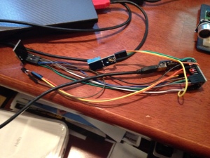
The first picture is the full prototyping setup, with the FTDI Friend (Adafruit) plugged in, so that I could do the programming and testing.
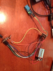
The second picture is with connections either soldered directly or using jumpers that will be hot glued in place.
Since I was using a sensor that was compatible with 5 volts, I simply soldered the sensor to the Pro Mini on the bottom of the board. Then I soldered on the 10k resistor to the data and vcc pin.
Next I wired in the nRF24L01+. This required a step power regulator, due to this unit running off of 3.3 volts. I hot glued the regulator to the back of the board, and soldered wires to the power-in pin on the nRF24l01+ (pin 2), and the VCC and Ground pins of the mini pro. The rest of the wires I used jumper wires and tied the nRF24L01+ to the Pro Mini using this diagram: Wiring the Radio
I did not have any handy 9 volt battery clips, so I direct soldered jumper wires to the battery, and power it off and on by removing the jumper wire to the Pro Mini .
This completes the steps for this build.
Components used in this sensor:
Arduino Pro Mini 5 volt
LE33CZ-AP 3.3 volt regulator (TO-92)
nRF24L01 RF Transceiver
DHT11 Temp/Humidity Sensor
9 volt battery
4.7uf capacitor (on power leads of the nRF24L01)
10k [brown,black,red] resistor (on DHT11 Power + Data leads)
In the next post, I will detail the process of building the Serial Gateway.


Recent Comments