rpiarduinomusings

Raspberry Pi, Arduino, Sensors and the data they produce

Monthly Archives: December 2015

Sensor Project – Moving Forward – Part 2

After the prior success of the PiDome installation (with a couple glitches) I was all ramped up to see the first sensor get installed, and was hopeful it would be simple.

I first went to the Raspberry Pi [RPi]  to hook in the Arduino Pro Mini to the USB port and boom,  The RPi immediately rebooted, taking down the PiDome with it. Bummer!

Apparently the voltage drop is such that the RPi sees it as a problem!  With research, it is indicated that it is best to use a powered USB hub if you are going to hotswap. So if you don’t want this to happen, plug and unplug the USB devices when powered down, or use a powered USB hub, or use the new B+ and Pi2 which manage this current fluctuation better. I also see where a larger amperage of power supply might also alleviate this, so that is another experiment to follow.

This does also point out that I need to investigate the way I start up the PiDome as well. When I found that i was starting before the eth0: has an IP, thus confusing the webserver component, I took it out of the init sequence, and now I think I need to resolve that such that it can be automated, if the RPi restarts and I am not there, everything will be offline. A quick search shows the newer option in the OS to allow the boot to “wait” for the network stratup to complete before finishing, so tnow I can go back and put the PiDome back into the init.d script!

Back to the task at hand, the gateway was attached, but not yet recognized, as seen by the command: lsusb, I see the ftdi friend, but not the Arduino Pro Mini and 12cdetect -y 1 shows no devices, so I have a new problem to research.

The overall approach I am taking is this:


PiDome toBe diagram

The lsusb check shows this:

lsusb

Now the 1c2detect shows nothing:

i2cdetect result

I will have to dig deeper to figure out why this is not being recognized, before any additional progress can be made.

My next step is to check the logs, and I find that indeed the system is finding the ftdi chip attached to my Arduino Pro Mini:

FTDI Uart Recognized

Now I will investigate how this uart is “spoken” to by PiDome.


Sensor Project – Moving forward

We have played quite a bit with the sensors to learn about the arduino and raspberry pi devices, as well as python and C code to get a feel for the programming.  I feel like this has been a useful endeavor, and feel far more educated on those topics, but it is time to move forward with the home control and sensor efforts, moving out of experimentation to implementation.

There are several established platforms the we have looked at to get a feel for  how we could implement, as well as for theory of operations.  Our group is a mixture of disciplines with both hardware, networking and software knowledge.  We also prefer open source tools.

Today, I decided to take the group down a path, one that I believe encompasses all of the desired outcomes we have discussed.

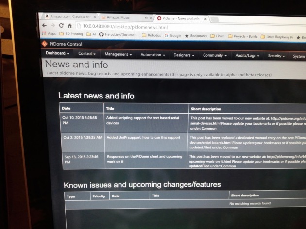
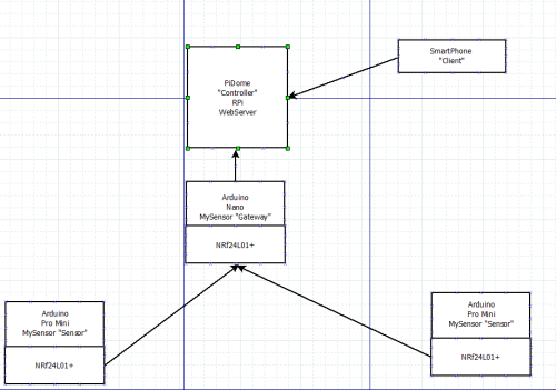
MySensors.org has been a constant reference during this learning phase, returning there every time a new sensor came up in our discussion. I have chosen this implementation for the sensors and gateway, along with the PiDome “controller” [www.pidome.org] running on the Raspberry Pi model 2 B.

My efforts now turn to installation of the base configuration of these.

  1. PiDome Controller installation and configuration.
  2. MySensors “Serial Gateway”
  3. Basic Sensors [(4)- Sound, PIR, Temperature/Humidity, Door/Window/Gate]

The following posts will document these efforts individually.

The first step is to create the controller environment. With the  PiDome selection made, you can proceed to download the PiDome installation.  It is not currently a selection that you can download as a pre-configured image, so you will have to build it out in successive steps.  You will start with a NOOBs install, per the Rapsberry Pi page here:

http://www.raspberrypi.org

I go to the downloads page from the menu, and choose the NOOBs item with a zip download, you can use whichever method works for you.

In my case, once the download concluded, I un-zipped the files into a spot in my download directory.

Now, NOOBs is not a burnable image, as we had done with prior installs of Raspberian, I do not know why, but I am sure they have a reason.

My next step was to insert an SD card into my USB adapter, and do the SD Format on it. [ http://www.sdcard.org%5D SD Formatter 4.0 is the tool I used.

Step two was to drag and drop all the files from the directory [I un-zipped into in the previous step] into the SD card.

Now eject the SD card on your computer, and place it back into the Raspberry Pi SD card slot.

Some assumptions here are that you have the keyboard, mouse, monitor and network connections all hooked up already to the Raspberry PI [RPi].

Time to boot the RPi.

When the screen appears, Clink the box for Raspbian and click on Install.

Be prepared to wait a while, as this is a network installation of the OS.

Once this process has concluded, go to the  PiDome Server installation page here:

http://pidome.org/support/server-install.html.

Pay attention to the details on the GPIO configuration, using this webpage:

http://elinux.org/RPi_Serial_Connection

At this point, I made no changes, as I think my gateway will be using the USB connection, so I will just bookmark this page for later in case I misunderstood the functionality.

I will not document each step of the PiDome here, as I was able to follow the support page exactly.

Key steps to note:

Create the directory on the PiDome SD card: /opt/pidome/pidome-server

Copy all the files from the zip file to this directory. I use the tool winsftp to accomplish this.  I did not know how to use winsftp with elevated permissions, so I copied the files off to /home/pi/Downloads via the windows tool, then went to a terminal window and used the cp command to get the files where they belonged [ /opt/pidome/pidome-server ].  I then followed the installation page to set the permissions in this directory.

Once that was completed, I updated the init.d to make the program start up on boot.  I rebooted a couple times, but each time the system failed to run properly.  I search for the appLog.txt file (found in the server directory btw) and discovered that it ran the first time, but took longer than I had patience for (it was setting up the DB) and my reboot did not help. The second time it tried t run but the system started up before the wifi was able to get a valid IP address!  I proceeded to remove the autostart, and decided to go to a manual start for now.  Boom, It Worked!  I now have PiDome running on my Raspberry Pi model B.

Next Steps will be to attach the MySensors.org gateway, and then deploy my first two sensors.  Watch for another installment soon!

PiDome-Success


Power – Arduino Low Power Sensors

Since we last visited the sensor network in mid-December, we have tested the range of the previously built sensors, by placing them into some cheap plastic food containers.

These were not meant to be low power items, more just to validate software and connectivity through the nrf24l01+ wifi units, back to the base Raspberry Pi (RPi).

This worked well as a validation for each subject area.  The next step was to try to determine if the Nrf24l01+ we sufficient for the  communications job.  One modification was that we had to move the receiver to near a window, to extend the range to 60-70 feet, which was successful.

That was the good news, the bad (but predicted) news was that a 9 volt battery did not last long in either the Uno based unit (15 hours) nor the Pro Mini unit (22 hours).

The next step was to either rewrite the code in these units to automatically power down and back up when we wanted to transmit, or to find ways to reduce the power used by the regulators and on-board LEDs.  I have chosen to go a slightly different way by re-embracing of the mysensors.org environment, then adjust what they deliver to the hardware I have in hand.

My first step has been to re-purpose the arduino pro mini  [PM5] (16mhz 5v) to be the serial gateway for this.  I was able to download and setup the “serial gateway” from their web site, and am proceeding to build a new sensor device to their specifications. The next step in this environment is to pick a controller.  The group has purchased Raspberry Pi units, so that will be the device to deploy to.


Sensor Network –First Deployment

Well, you have to start somewhere, so while this code is neither clean nor fully functional, it does demonstrate the functionality of the effort underway. This code reflect two sensors basically streaming their name and current info, and the receiver RPi scrolling the received info across the screen.

Also my first attempt at putting code in the blog, so we’ll see how it works.

The next code iterations will remove all the screen displays and move to writing a file with the sensor node name and accompanying data from the sensors to a comma deliminated file (.csv).

Arduino based sensors transmitting to the Raspberry Pi via NRF24L01+

This post shows two code blocks, one for any Arduino sensor node and the second is the RPi receiving code.
The Arduino Sensor Node Transmitter -Send-Recieve

#include #include #include // ce,csn pins RF24 radio(9, 10); void setup(void) { while (!Serial); Serial.begin(9600); radio.begin(); radio.setPALevel(RF24_PA_MAX); radio.setChannel(0x76); radio.openWritingPipe(0xF0F0F0F0E1LL); const uint64_t pipe = 0xE8E8F0F0E1LL; radio.openReadingPipe(1, pipe); radio.enableDynamicPayloads(); radio.powerUp(); } void loop(void) { radio.startListening(); Serial.println(“Starting Loop. Radio on.”); char receivedMessage[32] = {0}; if (radio.available()) { radio.read(receivedMessage, sizeof(receivedMessage)); Serial.println(receivedMessage); Serial.println(“Turning off the Radio.”); radio.stopListening(); String stringMessage(receivedMessage); if (stringMessage == “GETSTRING”) { Serial.println(“Looks like they want a string!”); const char text[] = “Hello World!” ; radio.write(text, sizeof(text)); Serial.println(“We sent our message.”); } } delay(1000); }

Raspberry Pi Gateway -Send-Recieve

import RPi.GPIO as GPIO from lib_nrf24 import NRF24 import time import spidev GPIO.setmode(GPIO.BCM) pipes = [[0xE8, 0xE8, 0xF0, 0xF0, 0xE1], [0xF0, 0xF0, 0xF0, 0xF0, 0xE1]] radio = NRF24(GPIO, spidev.SpiDev()) radio.begin(0,17) radio.setPayloadSize(32) radio.setChannel(0x76) radio.setDataRate(NRF24.BR_1MBPS) radio.setPALevel(NRF24.PA_MIN) radio.setAutoAck(True) radio.enableDynamicPayloads() radio.enableAckPayload() radio.openWritingPipe(pipes[0]) radio.openReadingPipe(1, pipes[1]) radio.printDetails() #radio.startListening() message = list(“GETSTRING”) while len(message) 2: print (“Timed out.”) break receivedMessage = [] radio.read(receivedMessage, radio.getDynamicPayloadSize()) print(“Received: {}”.format(receivedMessage)) print(“Translating our received Message into unicode characters…”) string = “” for n in receivedMessage: if (n >= 32 and n <=126): string += chr(n) print(“Our received message decodes to: {}”.format(string)) radio.stopListening() time.sleep(1)