So far in this series, I have show the build of sensors, and installed MQTT, configured Node-RED, and looked at a dashboard; cool, but now I want to control things external to my system.
I have read and viewed several blog pages and YouTubes of people using home-built and commercial products to accomplish this goal.
Today, using a couple new libraries, I am exploring the Sonoff 8266 based relay units. These are quite reasonably priced at $5-10 depending on where you procure them.

Disclaimer: I do not see an FCC marking nor a UL marking, so use at your own RISK.
Disclaimer 2: I am programming this test via the FTDI Friend by AdaFruit, and I have modified this unit to deliver 3.3 volts versus the default 5 volts it comes from the factory with. Make sure you cut the line on the 5 v pad on the back of the board, and solder the 3.3 v pads together or you risk damaging the sonoff unit. IF you are using a different unit, refer to the docvumentaiton that came with your unit to ensure you are only delivering VCC of 3.3 volts.
WARNING: Ensure you do not have any connectivity to the mains or AC voltage when you are doing this programming or wiring work! Only do the programming when you have no AC connections! You can damage yourself and your equipment if you do not take this precaution.
Okay, that out of the way, let me tell you the setup of this unit for programming.
- Open the Sonoff unit, remove the outer plastic shell to gain access to the board. You will be putting some type of connector onto the main board, which will allow your ftdi board to be connected. I used a breakaway type header I had on hand.
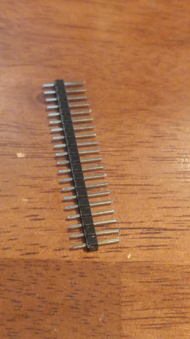
- Find the five pin holes in the middle of the board, and using putty or foam, hold the pin header in place and solder it up.

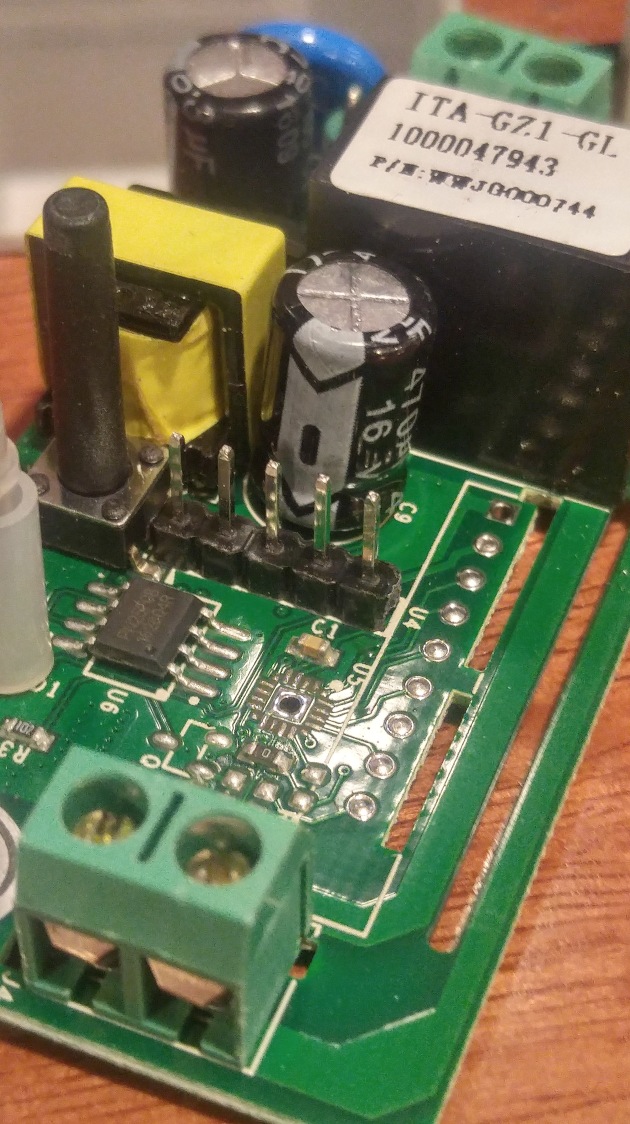
- Connect up the 3.3 v to pin 1 which is closest to the black switch. Connect up ground to pin 4.
- Connect up the TX from your ftdi to the TX on the Sonoff board, pin 3
- Connect up the RX from your ftdi to the RX on the Sonoff board, pin 2.
- Obtain the code and libraries from this site. I am using his connectivity and code for this example, and RUi’s site is a wealth of info that has helped my greatly along this journey!

- If you have not done so, go and setup the Arduino IDE for the 8266!
- Install Rui’s code, and make sure you modify it for you SSID and Password!
- Before connecting the ftdi board to your computer, make sure you setup the Sonoff in programming mode my holding down the black button, then plug the usb cable into the ftdi board.
- make sure you configure your IDE to use the generic 8266 board, and the right port for your ftdi cable.
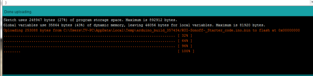
- Upload the code to your Sonoff, and wait for the programming to complete, you’ll see the IDE show 100% when it is done.
- Before disconnecting from the ftdi board, open the serial monitor and make sure the code is working, and that the Sonoff has connected to your wifi network.

- Now, disconnect the ftdi board and cabling, and re-assemble the unit in the protective case, and make sure your AC wiring is correct, or get a person who is familiar with AC wiring to get you hooked up to mains power. I used a three prong extension cord and split it in half, attaching the plug in to the input side of the Sonoff, and the socket to the Output side of the Sonoff.
- Now you can plug it up! I used a desk lamp that was handy, and once plugged in, open a web page to the IP address obtained in step 12 above.
- Play with the web page, if you have wired it correctly, your lamp should power off and on with the buttons on this page.

Well, we are done with this step, we have control of the real world from the Sonoff.
The next installment will be to reprogram the Sonoff to use MQTT subscribe to accept commands, and to use MQTT publish commands to communicate the status of the unit!

Recent Comments